Wire rope diameter
A distinction is made between the nominal rope diameter and the effective rope diameter. The nominal wire rope diameter is an agreed theoretical value for the diameter of the smallest circle circumscribing the outer strands.
The effective rope diameter, also called actual rope diameter, is the diameter of the smallest circle enclosing all outer strands, as measured on the rope itself. The tolerance range for the effective rope diameter is specified in related national and international standards. According to EN 12385-4 it is between -0% and +5% (for nominal rope diameters ≥ 8mm)
This means that the effective rope diameter upon delivery must neither be smaller nor bigger than 5% than the nominal rope diameter. The tolerance range is often higher for smaller ropes like 3mm to 7mm nominal diameter. In the Oil and Gas industry, which is firmly based on US regulations, a tolerance range from -1% to 4% is applied. The effective rope diameter changes depending on the load applied. Therefore the effective rope diameter should in critical cases be measured on a rope that is loaded with 5% of the calculated breaking strength. verope® produces standard tolerances of +2% to +4% and special tolerances upon request.
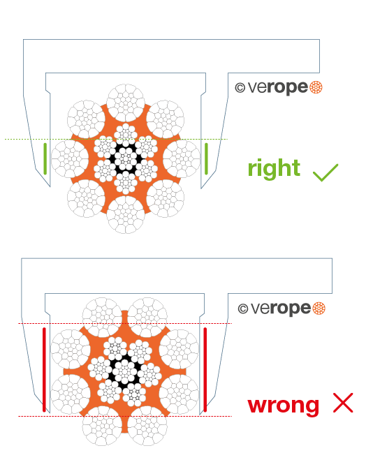
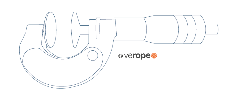
Measuring devices and their correct handling
In order to define the correct effective rope diameter, the correct measuring device has to be used. The measurement should strictly be done over the round ends (circumscribed circle of the rope). If one measures in the strand valleys, the result will be inacurate. For ropes with an uneven number of outer strands, it is important that the measuring surface covers several strands (figure 10).
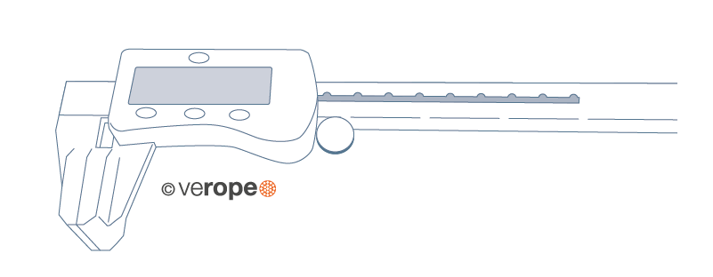
Types of measuring devices

Lay direction of a wire rope
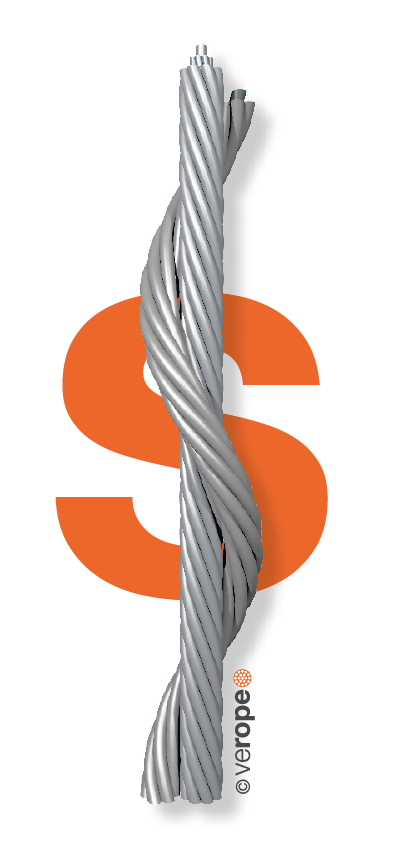
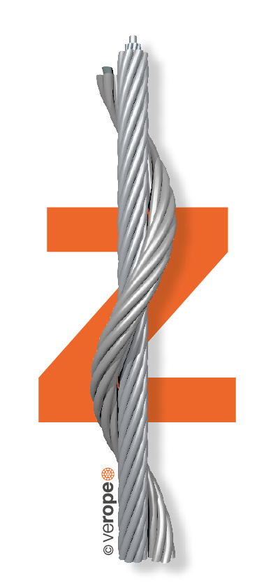
A distinction is made between right hand and left hand lay ropes. The lay direction is left hand, when the strands (moving away from the beholder) are rotated counterclockwise (figure 14). The lay direction of a rope is right hand, when its strands (moving away from the beholder) are rotated clockwise (figure 15). The lay direction of a rope is often given by a capital S for the left hand lay rope and by a capital Z for the right hand lay rope. Others often use RH for Right Hand and LH for Left Hand lay ropes.
Rope design
By the design of a wire rope, one understands the formation principle according to which the elements of the wire rope (the wires and the strands) are arranged relative to each other. The designation of a fiber core is FC, for an independent steel wire rope core it is IWRC. As an example all round strand ropes of the 6×19 Warrington design with a fiber core have the construction 6 x [1-6-(6-6)] – FC.
Fill factor of a rope
The fill factor of a rope is defined as the ratio of the metallic cross section of the rope (or a simplified calculation of the sum of the single wire cross sections) related to the nominal rope diameter. The fill factor specifies which amount of space the wires and strands take in the rope (figure 16).
The fill factors of the most common ropes are between 0,46 and 0,75. This means, that the amount of steel in the rope volume is about 46% to 75%. Wire ropes with a wire rope core have higher fill factors than ropes with a fiber core.
A rope of the design 6×25 Filler-FC for example has a fill factor of 0,50 and a rope with a design 6×25 Filler-IWRC has a fill factor of 0,58.
Usually fill factors of wire ropes with a fibre core (FC) decrease with an increasing number of outer strands. A rope of the design 6×25 Filler-FC has a fill factor of 0,50, a rope of the design 8×25 Filler-FC has only a fill factor of 0,445.
Usually fill factors of wire ropes with a wire rope core increase with an increasing number of outer strands. A rope of the design 6×25 Filler-IWRC has a fill factor of 0,58 and a rope of the design 8×25 Filler-IWRC has a fill factor of 0,587.
Wire ropes that are made of compacted strands have higher fill factors than ropes of uncompacted strands. By compacting and rotary swaging of the rope itself the fill factor can further be increased.


Lay types of wire ropes
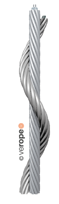
Two lay types are to be considered: Regular or ordinary lay and lang’s lay. In regular lay ropes, the lay direction of the wires in the strands is opposite to the lay direction of the strands in the rope. We distinguish between right hand ordinary lay RHOL (right hand strand, left hand rope, zS) (figure 17) and left hand ordinary lay LHOL (left hand strand, right hand rope, sZ) (figure 18). In lang’s lay ropes, the lay direction of the wires in the strands is equal to the strands in the rope. We distinguish between left hand lang’s lay LHLL (left hand strand, left hand rope, sS) (figure 19) and right hand lang’s lay RHLL (right hand strand, right hand rope, zZ) (figure 20).
The advantages of regular lay ropes are:
• Better structural stability
• Higher number of broken wires are allowed
• Easier identification of broken wires
The advantages of lang’s lay ropes are:
• Better contact in the groove of the sheaves
• Superior resistance to wear
• Longer lifetime in case of high dead loads
• Considerably better spooling behavior on a multi-layer drum
Low-tension wire ropes
In the stranding process the initially straight wires are forced into a helical or double-helical form. Therefore, the wires in a rope are always under tension, even in an unloaded rope. Such a rope must be sealed very tightly left and right of the joint before cutting the rope because otherwise the free ends of the wires will spring open. By using a “preforming tool”, the wires and strands can be heavily plastically deformed during the stranding, so are laying nearly without tension in the rope, the rope now is preformed. The ropemakers consider such ropes to be “dead”. Preformed ropes can be cut much easier, also secured by seizings of course, than nonpreformed ropes.
Types of rope cores (abbreviated designations according to EN 12385-2)
Usually wire ropes have either a fiber core (FC) or a steel/wire core. The steel/wire core can be a strand (WC) or a small rope, named as independent wire rope core (IWRC). The IWRC can be made in a separate operation or during the closing operation of the wire rope (PWRC). The wire core can also have a plastic coating (EPIWRC). Cores made of compacted strands have the additional designation (K). An independent wire core made of compacted strands is therefore called IWRC (K). A rope closed in a single operation and made out of compacted strands both in the core and the outer strands is called PWRC (K).
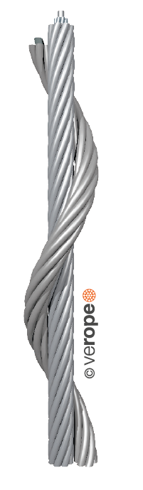
Semi rotation-resistant wire ropes
wire ropes and their free rope end rotate to a greater or lesser extent around its longitudinal axis under the influence of tension. Wire ropes having a core lay direction opposite to the lay direction of the outer strands and 3- or 4-strand regular lay wire ropes rotate considerably less than wire ropes with the same lay direction of the wire core and the outer strands and wire ropes with fiber cores. According to VDI 2358, a wire rope is semi rotation-resistant when: “the wire rope which turns around its longitudinal axis when subjected to unguided load and/or hardly transmits a torque to the attachment at the end in the event of guided rope ends.”
According to ISO 21669 and DIN EN 12385-3: “a rope is considered to be semi rotation resistant if it rotates at least once and at most four times around its axis at a length of 1000 x d under a load of 20 % of the minimum breaking force. In terms of rotation angle, the defined limits are between 360° and 1440°.”
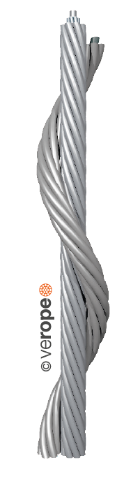
Rotation-resistant wire ropes
According to the regulation of VDI 2358, a wire rope is rotation-resistant, when: “the wire rope, which hardly turns around its longitudinal axis when subjected to unguided load and/or hardly transmits a torque to the attachment at the end in the event of guided rope ends.”
According to ISO 21669 and DIN EN 12385-3: “a rope is considered to be rotation resistant if it rotates around its axis at most once at a length of 1000 x d under a load of 20 % of the minimum breaking force. The rotation can be exhibited here in rope closing or rope opening sense. For the rotation angle, this implies: between -360° and 360°” (figure 21).
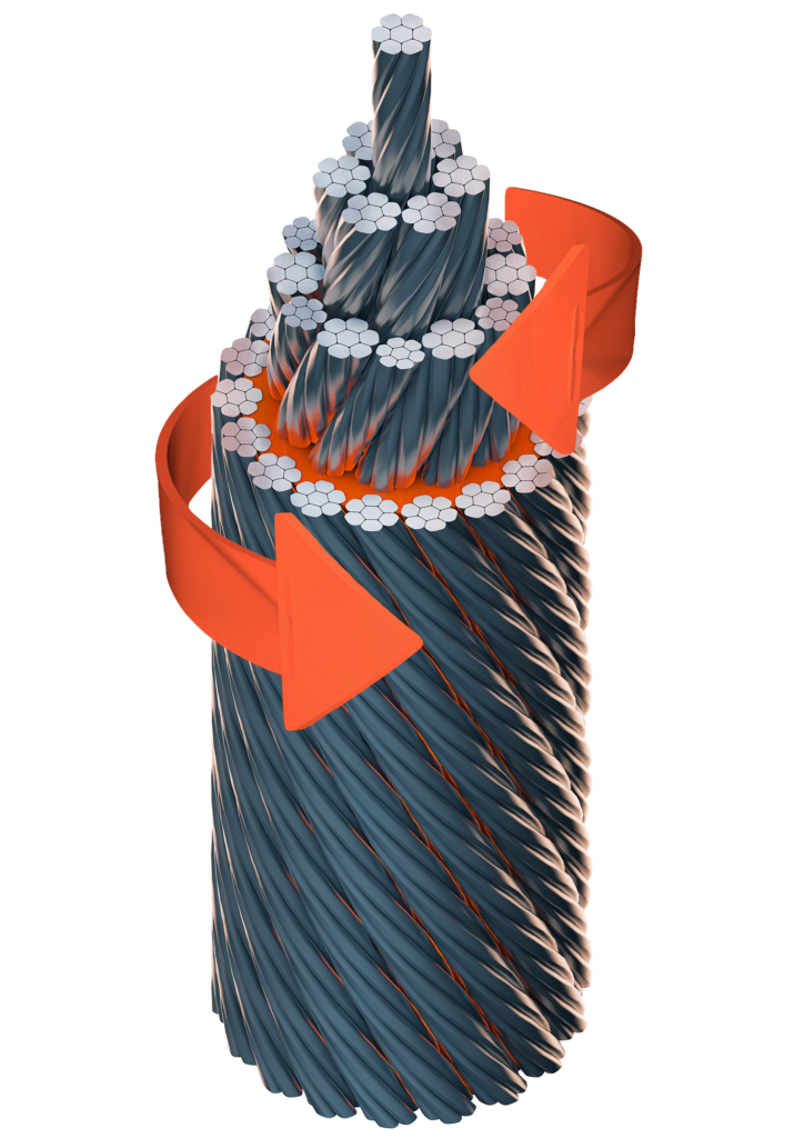
Figure 21: Rotation-resistant rope verotop P: the
torques of the rope core and the layer of outer strands,
generated under load, work in opposite directions
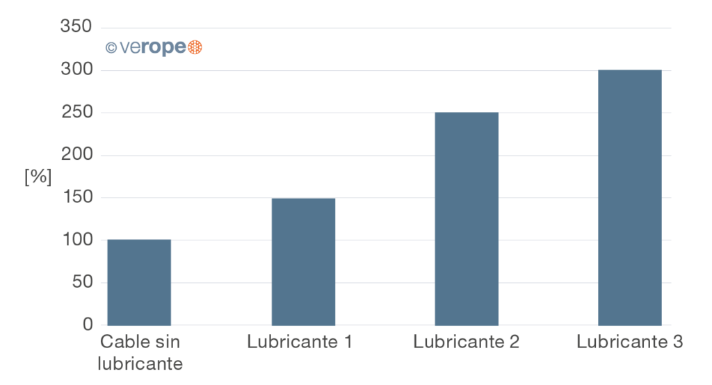
Wire rope lubricant

The wire rope lubricant has two major tasks: it should protect the rope from corrosion and minimize the friction between the rope elements themselves and between the rope and the sheave or the drum. A reduction of the friction reduces the actuating power and minimizes the wear of the rope, the sheaves and the drums. We differentiate between wax-based lubricants and oil-based lubricants. While wax-based lubricants offer a better handling of the ropes, the oil-based lubricants advantage is a better closing of the lubrication film due to the gravitational force of the oil. The quality of the wire rope lubricant has a great impact on the fatigue resistance of a wire rope (figure 22).
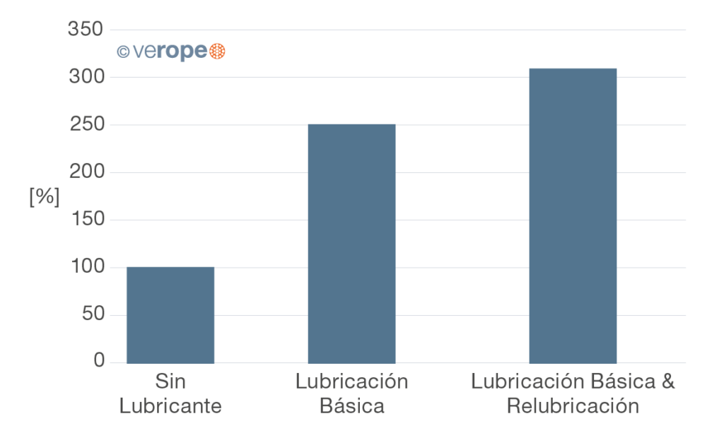
Re-lubrication
Generally wire ropes are lubricated intensively during the production process. Nevertheless, this initial lubrication has to be renewed regularly during the whole rope’s lifetime. A regular re-lubrication contributes to an increase in the rope’s service life (figure 23). The lubricant used for re-lubrication needs to be compatible with the lubricant used during production. It is advised to follow the maintenance instructions in ISO 4309.