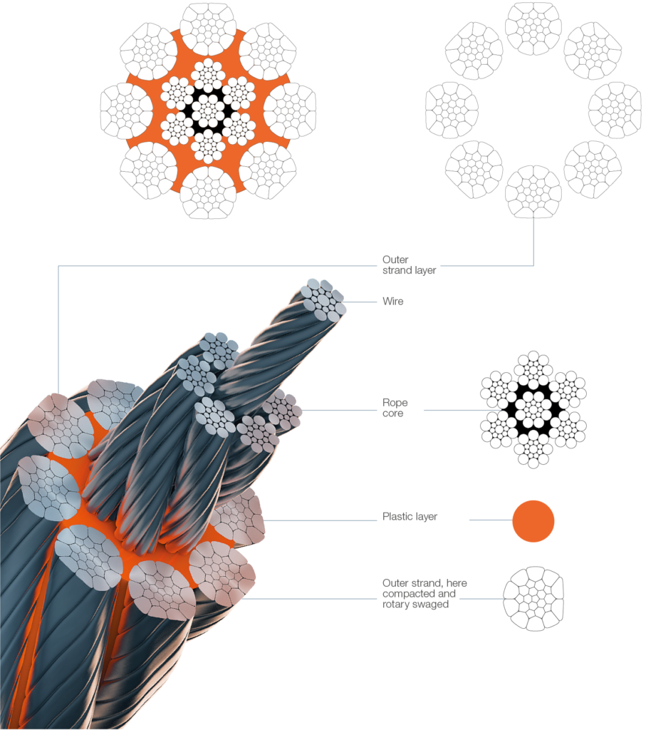
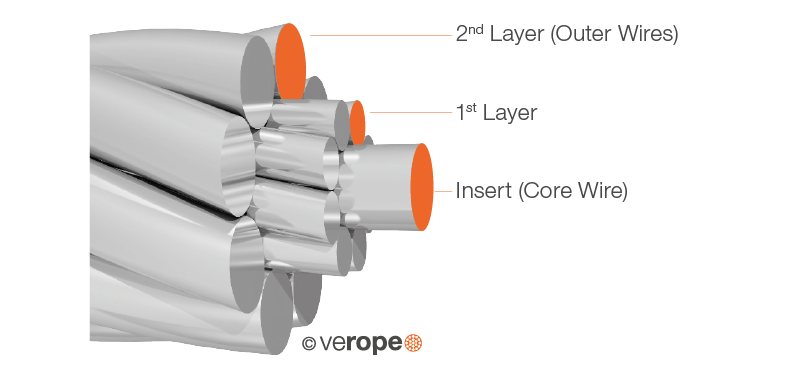
A strand consists of one or multiple layers of wires, which are wound in a helical shape around an insert (figure 1)
Lay length of a strand
The lay length of a strand is generally understood as the pitch of the helical lay of the wires, which means the lengths of a strand at which the wire circulates completely one time. By varying the lay length, the contact conditions of adjacent wires, the elastic properties and the breaking strength of a strand can be changed.
By varying the lay length, the contact conditions of adjacent wires, the elastic properties and the breaking strength of a strand can be changed.
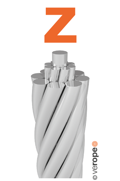
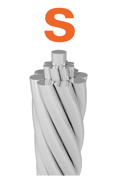
Lay direction of a strand
A distinction is made between right hand and left hand lay strands. The lay direction is left hand, when (moving away from the beholder) the wires are rotated counterclockwise (figure 2). The lay direction of a strand is right hand, when its wires (moving away from the beholder) are rotated clockwise (figure 3). The lay direction of a strand is often given by small s for the left hand lay strand and by a small z for the right hand lay strand.
Diameter of a strand
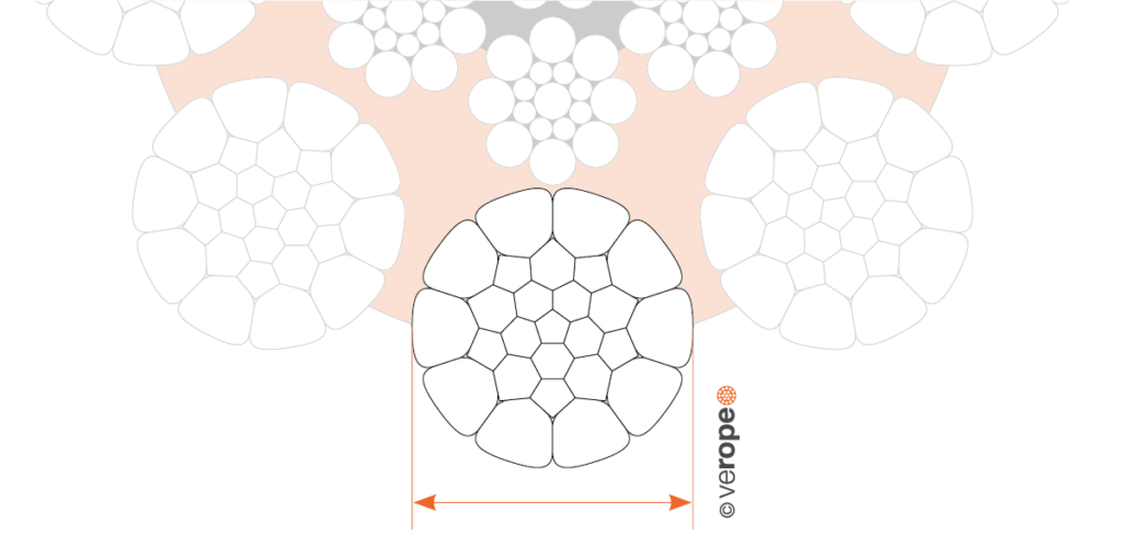
The diameter of a strand is the diameter of the smallest, all wires enclosing enveloped circle. The strand diameter is usually measured with a micrometer caliper and is given accurate to 1/100mm (figure 4).
Strand design
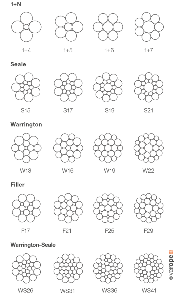
One understands the formation law by the design of a strand according to which the wires are arranged relative to each other. So all strands of the design Seale have for example the construction 1 – n – n (with n=3, 4, 5, 6, 7, 8, 9) wire layers, which get stranded parallel to each other in a single operation. According to EN 12385-3 these are connected by a minus “-” sign in the designation.
The name of a Seale strand design Seale 17 is therefore 1-8-8, the designation of a strand design Seale 19 is 1-9-9.
Thre moost im8portant strand designs are one-, two and three layer standard strands (figure 5), as well as parallel lay strands of the strand designs Seale, Filler, Warrington and Warrington-Seale (figure 6 & 7).
The two and three-layer standard strands show crossovers between the wires of the different wire layers (figure 5). Here the wire layers get stranded in separate operations in the same direction (designation N) with a same stranding angle but with different lay lengths.
The so called parallel lay strands (Seale, Filler, Warrington, Warrington-Seale) avoid crossovers and create line contact of the wires instead. This happens due to a stranding of all wire layers at once with different stranding angles but the same lay length (figure 6 & 7).


Compacted round strands
A compacted round strand starts as a conventional torsion free round wire strand. The strands are compacted either during stranding or in a separate operation afterwards to form a smaller diameter by rolling or drawing. The originally round wires are heavily deformed by both the compacting tool and the adjacent wires (figure 8).


Fill factor of a strand
The fill factor of a strand is defined as the ratio of the metallic cross section (or as simplified calculation the sum of the single wire cross sections) related to the area of the smallest circle enclosing the strand. The fill factor specifies the amount of space which the strand takes in the rope meaning the quantity of steel.
The fill factors of the most common strands are between 0,70 and 0,82. This means, that the amount of steel in the strand is about 70% to 82%. The fill factors of strands can be considerably increased by compacting.
Usually the fill factor of a strand increases with an
increasing number of wires. A Seale 15 strand (1-7-7) for example has a fill factor of about 0,77 and a Seale 19 strand (1-9-9) has a fill factor of about 0,79.