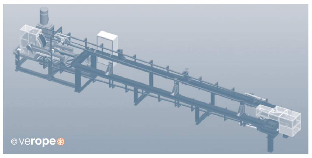
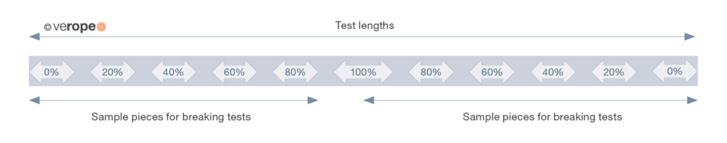
verope operates the first two bending fatigue machines world-wide built according to a revolutionary concept. The steel wire rope is installed in the test machine, put under tension, and then the rope travels back and forth over five test sheaves until it finally breaks in the middle. Only then the rope analysis starts: To the left and to the right of the broken section, which during the test has travelled back and forth over five sheaves, the machine has rope sections which only travel over four sheaves and don’t make it to the fifth. Regardless of what the number of cycles to failure will be, these sections will always have made 80% of this number. These sections, and the further sections which will have travelled over 3, 2, 1 and 0 sheaves only and which will represent the condition of the rope after 60%, 40, 20% and 0% of the rope life are cut out for analysis (figure 35).
One of the two sections of each condition is used to determine the number of external wire breaks and the changes in rope diameter and lay length. Then the section is taken apart in order to also determine the number of internal wire breaks on the underside of the outer strands, on the outside and inside of the IWRC and on individual strands as well as changes in the IWRC and strand diameters and lay lengths. This way the sections will tell you how the external wire breaks develop over the lifetime of the rope, how the internal wire breaks develop over time, how the plastic infill looks at different stages of the rope life and which elements start to deteriorate first. These results can help verope. to improve the product design of a new ope after only a single test. The comparable 80%, 60%, 40%, 20% and 0% sections on the other side of the break are subjected to pull tests to destruction. This way verope. can determine how the strength of this rope design, its modulus of elasticity and its elongation at break develops over the lifetime of the rope. A steel wire rope should have a breaking strength as high or higher than new until it reaches the discard number of wire breaks (figure 34).
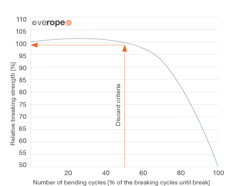
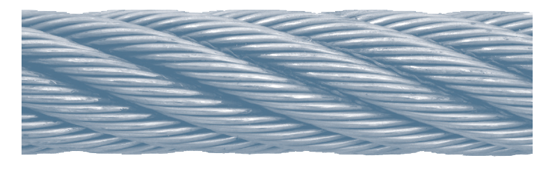
Figure 36: Condition at 0% of the bending cycle until breaking point
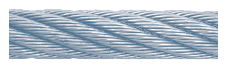
Figure 37: Condition at 20% of the bending cycle until breaking point
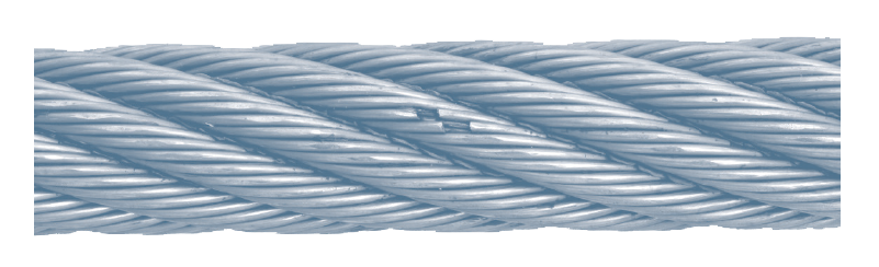
Figure 38: Condition at 40% of the bending cycle until breaking point
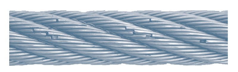
Figure 39: Condition at 60% of the bending cycle until breaking point
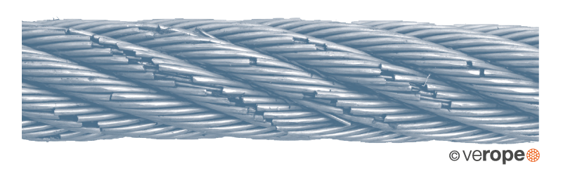
Figure 40: Condition at 80% of the bending cycle until breaking point
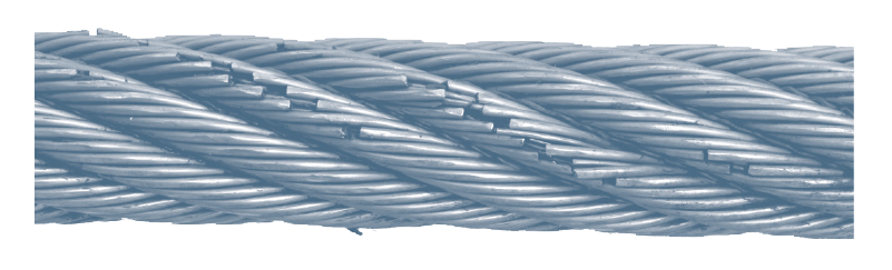
Figure 41: Condition at 100% of the bending cycle until breaking point
Due to the detailed analysis of the several working sections, the development of external wire breaks over the lifetime can be evaluated very precise (figure 42).
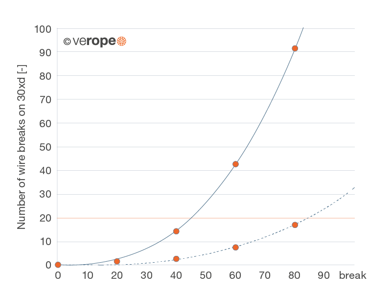
figure 42: Number of visible (pulled trough line) and invisible wire breaks (sketched line) dependent on the rope lifetime. After the ending of the bending fatigue test the analysis of the rope sections with the different fatigue numbers shows the marked numbers of wire breaks.
On disassembling the rope pieces the internal wire breaks depending on the lifetime can be evaluated (figure 43). At the veropro 8 construction the number of visible wire breaks is higher than the number of internal (invisible) wire breaks.
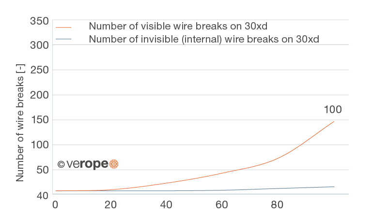
Figure 43: Development of the visible wire breaks on the wire rope surface and the wire breaks inside the rope that are visible from outside
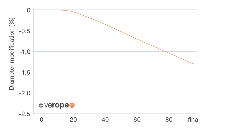
Figure 44: Diameter modification of the rope in the bending fatigue test
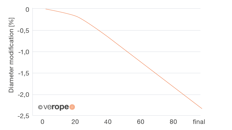
Figure 45: Diameter modification of the steel rope core in the bending fatigue test
Bending fatigue tests are taken normally until the break of the rope or a strand. The exact point of discard can be determined by evaluating the single rope sections.
This results in the so called “rest-lifetime” (lifetime between discard and break) (figure 46).
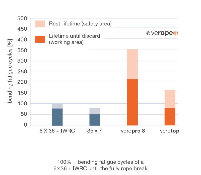
figure 46: Number of bending cycles until discard and until break
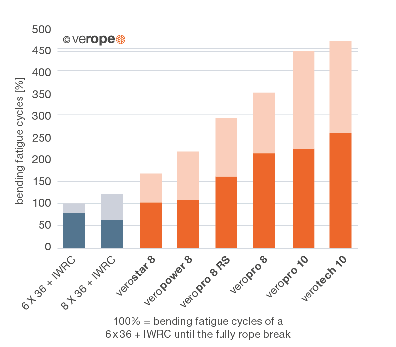
figure 47: Number of bending cycles until discard and until break (non-rotation resistant ropes, equal load)
figure 48: Number of bending cycles until discard and until break (rotation-resistant ropes, equal load)
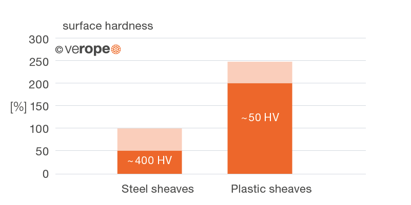
Bending fatigue when using steel or plastic sheaves
The lifetime of a rope is significantly influenced by the sheave material. By the use of plastic sheaves the bending fatigue rises clearly in comparison to the use of steel sheaves. The remaining “rest-lifetime” of the rope after the achievement of the discard criteria until the break of the rope, is with regard of the bending cycles more or less the same, nevertheless it drops significantly in percentage. Therefore the rope inspection must be carried out especially carefully when using plastic sheaves. verope recommends plastic sheaves, hence, only in applications where the ropes are checked magnet-inductively or where the rope gets damaged primarily outside like in multi-layer spooling (figure 49).
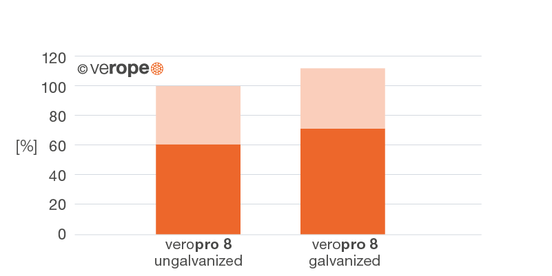
Bending fatigue of ungalvanized and galvanized ropes
A comparison of the bending fatigue of ungalvanized and galvanized ropes until the achievement of the discard criteria according to ISO 4309 and until break of the rope shows, that galvanized ropes usually reach more bending cycles. The zinc coating offers better “emergency operating features” when the rope is not lubricated any more and protects the rope from friction corrosion (figure 50).
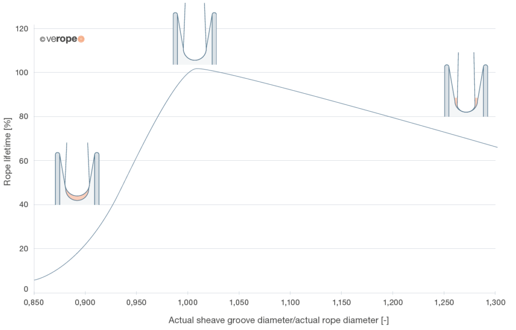
Bending fatigue in dependence on the groove diameter
According to ISO 4309 the groove of a sheave should have a diameter, that is 5% to 10% bigger than the rope diameter. During the operating time, the rope diameter will decrease. With this decreased diameter the rope will dig itself in the sheave groove and will reduce the groove diameter. Therefore, with the installation of the rope it should be considered, that the groove diameter of the sheave is at least 1% bigger than the measured rope diameter. If the groove diameter is too big, the support of the rope is not very good anymore and the surface pressure increases. Consequently the lifetime of the rope decreases steadily with an increasing groove diameter. If the groove diameter is too small, the rope will be squeezed and the lifetime d Steel sheaves rops extremely.
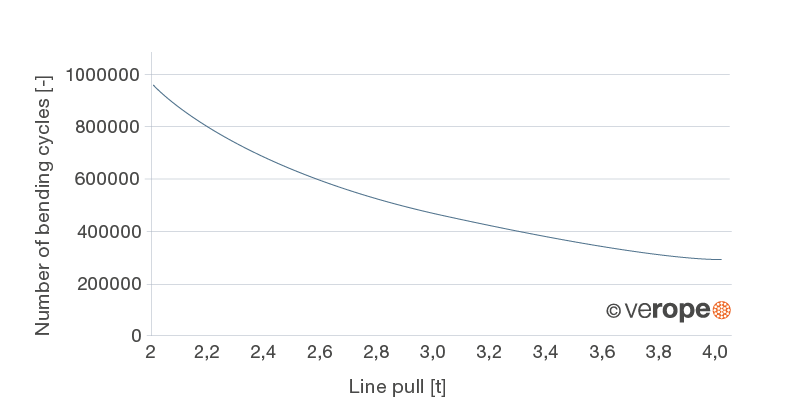
Bending fatigue in dependence on the line pull
The appealing line pull has a considerable impact on the bending fatigue. While for example with a line pull of 2t, still 950.000 bending cycles are reached, with a line pull of 4t only 290.000 bending cycles are reached (figure 52).
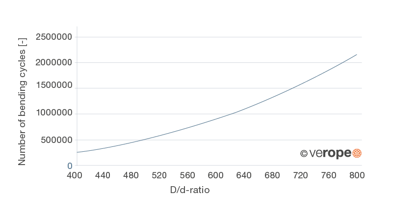
Bending fatigue in dependence of the sheave diameter
The applied diameters of the sheave as well as the diameters of the drums have a huge impact on the lifetime of a rope. In the shown example a rope running over a sheave with a diameter of 800mm still reaches more than 2.000.000 bending cycles, the bending condition reduces by halving the diameter of the sheave to 400mm to 290.000 bending cycles (figure 53).